Agent-native CAD / CAM · exact B-rep · extends itself · free for non-commercial use

CAD that talks back.

Say what you want and it gets built. Point at what you mean and it gets changed. Sketch, constrain and tweak by hand when that is quicker. Assemble it, section it, make it move, render it. Then STEP, STL, shop drawings, or G-code, and run it on your Makera Z1 (experimental). One reproducible script, on your own machine — and when the app lacks a tool, the agent writes it.

The tour — one real session with the real agent, only the thinking time sped up

Sound on. A real session with the real agent; only the thinking time is sped up.

Describe a part in plain wordsPoint at faces, edges and bodies in chatSketches with constraints and driving dimensionsFusion-style toolbar: press/pull, holes, fillets, revolve, loft, sweep, mirror, patternDesign Kit: screws, bearings, gears, motors by nameJoints, gear ratios, exploded views, studio renderSection analysis and interference checkISO and inch threads · mm or inchesExact STEP, STL, shop drawingsSlice with your OrcaSlicerExperimental CAM with simulation, setups and 4th axis · Makera, Haas and LinuxCNC postsExtensions: the agent adds tools and panels to the appUnit tests and graded agent evals Describe a part in plain wordsPoint at faces, edges and bodies in chatSketches with constraints and driving dimensionsFusion-style toolbar: press/pull, holes, fillets, revolve, loft, sweep, mirror, patternDesign Kit: screws, bearings, gears, motors by nameJoints, gear ratios, exploded views, studio renderSection analysis and interference checkISO and inch threads · mm or inchesExact STEP, STL, shop drawingsSlice with your OrcaSlicerExperimental CAM with simulation, setups and 4th axis · Makera, Haas and LinuxCNC postsExtensions: the agent adds tools and panels to the appUnit tests and graded agent evals
Get started

One download and one sentence.

  1. Download the app for macOS or Windows and open it.
  2. Install Claude Code, Anthropic's free command-line tool, and sign in once. The app is not allowed to bundle it, so on first launch it shows the exact command and checks for you.
  3. That's the setup. Everything runs on your machine; nothing leaves it except the conversation with Claude.
  4. Type your first part. Something like this, and watch it appear:
your first messageMake a 60 × 40 × 8 mm mounting plate with four Ø5 holes 8 mm in from each corner and a Ø20 boss 15 mm tall in the middle with a Ø8 through bore.
Watch this exact session as a tutorial →
AgenticCAD latest · desktop appreleased
Free for personal, hobby, research and educational use
A$99 + tax per user, per year for commercial use · buy licences

Needs Claude Code. The app does not bundle Anthropic's Claude Code; install it once (free, one command) and sign in with your Claude account or API key. The app walks you through it on first launch. Details.

Intel Macs and Linux: use the source zip for now.

Prefer to run from source? Linux, Intel Mac, or hacking on it.
# any platform with Python 3.12, inside the unzipped source zip or a clone of github.com/agenticcad/agenticcad
python3 -m venv .venv && .venv/bin/pip install -r requirements.txt
.venv/bin/python server.py        # then open the address it prints in your browser

Same app, same Claude Code requirement. All releases: github.com/agenticcad/agenticcad/releases.

Free for non-commercial use under PolyForm Noncommercial 1.0.0. Commercial use is A$99 per user per year; see licensing.

Step 1 · Create a model

Describe it. Point at it. Tweak it.

Three ways to shape a part, and they all end in the same place: one build123d script that the exact kernel executes. No feature tree, no hidden state, nothing you cannot read.

01

Describe

“60 × 40 × 8 plate, four Ø5 holes 8 mm from the corners, a Ø20 boss with a Ø8 bore.” Attach a photo or a napkin sketch if you have one. The agent writes the model with named dimensions.

02

Point

Click a face, an edge or a body and it becomes a chip on your message, with its exact type, centre, normal and size. The agent works on that face, not a guess.

03

Tweak

Press/pull, holes, fillets, chamfers, shells, revolve, loft, sweep, mirror and pattern from a Fusion-style toolbar; sketches with constraints; or change a number in the Parameters card. Written into the same script, undoable, visible to the agent.

Live · real kernel output

Point at a face. See what the agent sees.

This viewer runs the app's renderer on meshes baked from the real kernel. Hover and click faces: the chip and the [Selected geometry] block are exactly what a chat message carries.

design.pybuild123d · exact
Viewer
loading…
click a face to add a selection chip…
Put a 1 mm chamfer on the outer edge of this face.Send
# what the agent receives with your message [Selected geometry] (click a face)

Because the message carries the geometry, the agent can write faces().sort_by_distance((x, y, z))[0] and hit the face you meant, then confirm with inspect_model or a screenshot. Every rebuild renumbers faces, so the app matches chips again by type and centre.

Play the “point at a face” tutorial →
Manual, still code

“I just want to tweak it.”

Sometimes you know exactly what you want and do not want to say it. The toolbar works like a desktop CAD tool: pick, type a number, ↵. A command dialog walks you through each tool with a live prompt, chips for what you picked and unit fields. Under the hood the operation is appended to the body's expression in the script, so it is undoable, reproducible and visible to the agent.

_plate = plate.part
_plate2 = _plate + extrude(_plate.faces().sort_by_distance((7, 0, 19))[0], amount=5, dir=(0, 0, 1))
_plate3 = tap(_plate2, "M4", at=(18, 0, 4), depth=6, axis=(0, 0, -1))
result = {"Plate": _plate3.fillet(2, [*_plate3.faces().sort_by_distance((7, 0, 24))[0].edges()])}
Play the ribbon tutorial →

Hover a tool. Shortcuts match the app: B C O K create, Q H F X L V modify, I measure, D drawings, P slice.
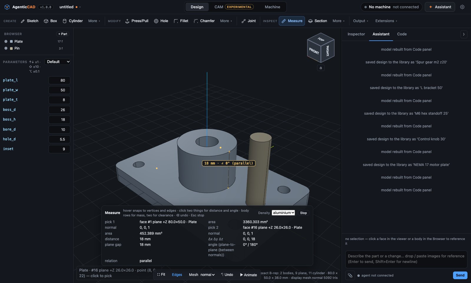
The Parameters card under the Browser and a live measurement between two faces
Sketch with constraints: H/V appear as you draw, dimensions drive, a dragged corner keeps the rules
Sketching

Constrain it. Dimension it. Drag it.

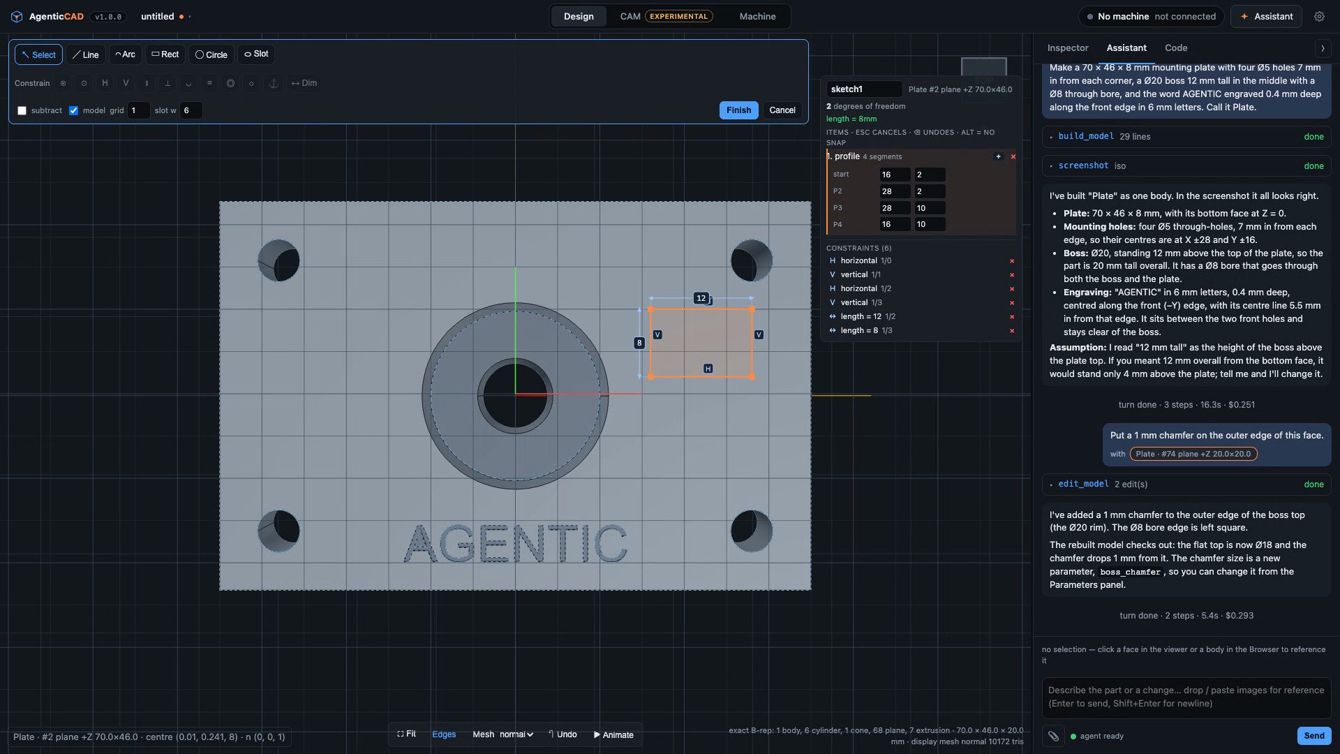
Lines and arcs snap to the model; horizontal, vertical and coincident constraints appear as you draw. Pick an edge, press D, type a number and the geometry moves to match. The status line counts the degrees of freedom left; fully constrained items turn white, and anything that conflicts is refused with a reason. Finish writes the sketch and its constraints into the script, where the agent can extrude, cut, revolve or loft it.

Play the constraints tutorial →

Sketches with constraints

Select a face, press K: lines, arcs, rectangles, circles and slots with snapping. Coincident, horizontal, vertical, tangent, equal, concentric… and dimensions that drive the geometry. Drag a point and the solver keeps every rule. It is also a real Sketch the agent can extrude, cut or revolve.

Metric and inch threads

ISO metric (M4) and Unified inch (1/4-20, #10-32): tap drill, clearance, hex and socket heads, nuts and washers from the tables. tap(part, "M4", …) cuts the hole and drawings call it out as M4×0.7.

Parameters, configurations, measure

Every top-level number is a field. Named configurations override them: pick a variant to rebuild, export every variant as STEP or STL in one go. Measure snaps to vertices, edges and faces: lengths, radii, angles, hole spacing, mass, clearance between bodies.

Exact B-rep, not triangles

Planes, cylinders, cones, spheres, tori and B-splines from OCCT. The display mesh has exact normals; the geometry underneath is analytic.
Step 2 · Print it, or document it

Send it to the printer, or to the shop.

Most parts stop here. File ▸ Export gives you what a slicer or another CAD package needs, and one press of Output ▸ Drawings turns the model into a drawing you can hand to someone.

  • STL for 3D printing, tessellated only at export, at the resolution you choose in the dialog (or the agent picks a tolerance). One file for everything or one per body, so multi-part prints come out as separate meshes.
  • Slice without leaving the app: if OrcaSlicer (or Bambu Studio) is installed, set your printer, filament, layer height, infill and supports once in Settings, hit Output ▸ Slice, and the layers appear in the viewer with a slider, feature colours, time and filament estimates, plus G-code and 3MF. Or just say “slice this for my Ender 3 at 0.28 mm”.
  • STEP, exact: cylinders stay cylinders and bodies stay separate solids, so it opens cleanly in Fusion, FreeCAD, SolidWorks or a supplier's quoting tool.
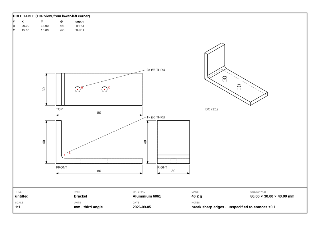
  • Shop drawings from the exact model: third-angle front, top, right and iso with hidden lines, overall dimensions, hole callouts and a lettered hole table, title block with mass and scale. SVG and DXF.
  • Ask for it: “export an STL at 0.05 mm for the Pin only” or “make drawings in aluminium” works too, because export and drawings are agent tools.
Export details in the docs →
Automatically generated shop drawing
Step 3 · Assemble, check, animate

Build the whole machine, then look inside it.

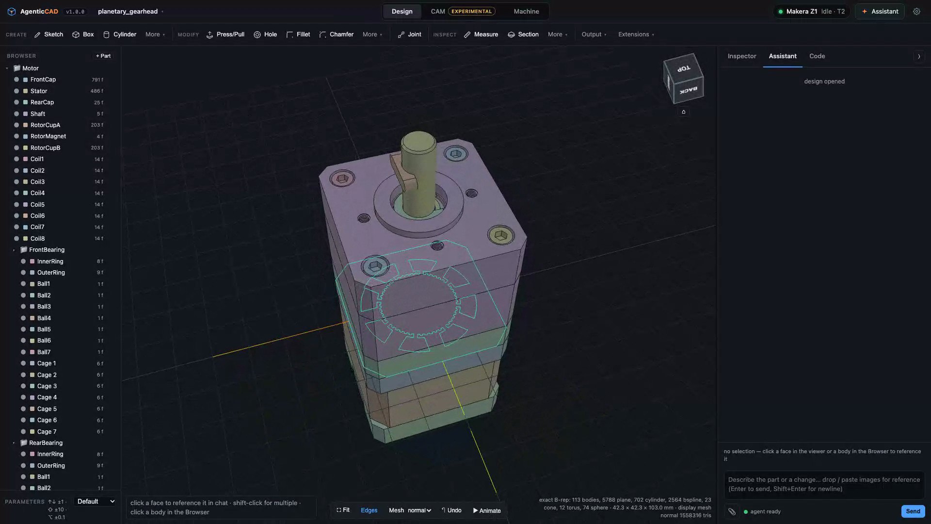
The planetary gearhead below is 113 parts the agent built from one prompt: ISO screws with real threads, ball bearings with balls and cages, phased planets, all from the Design Kit. Then it checked every pair of parts for interference and declared the joints so it turns.

Section analysis: cut with any plane, hatched caps, slide through

See inside

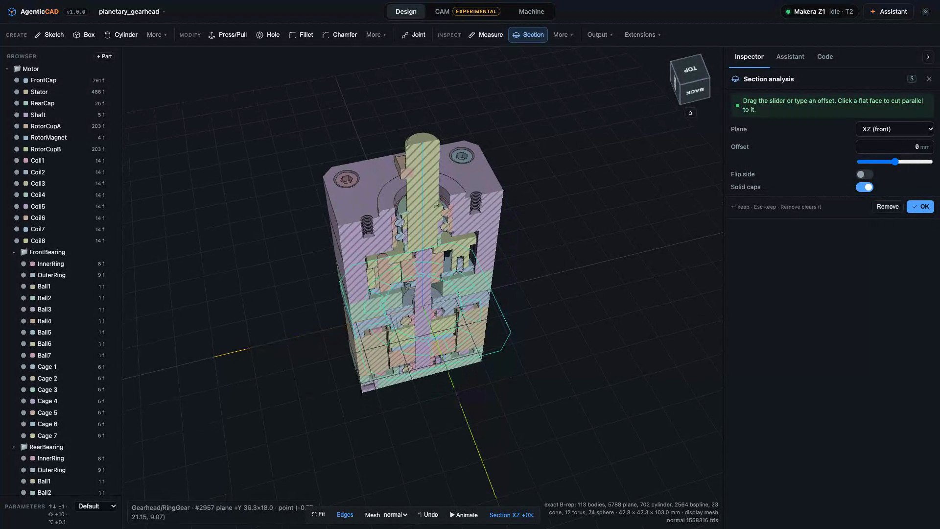
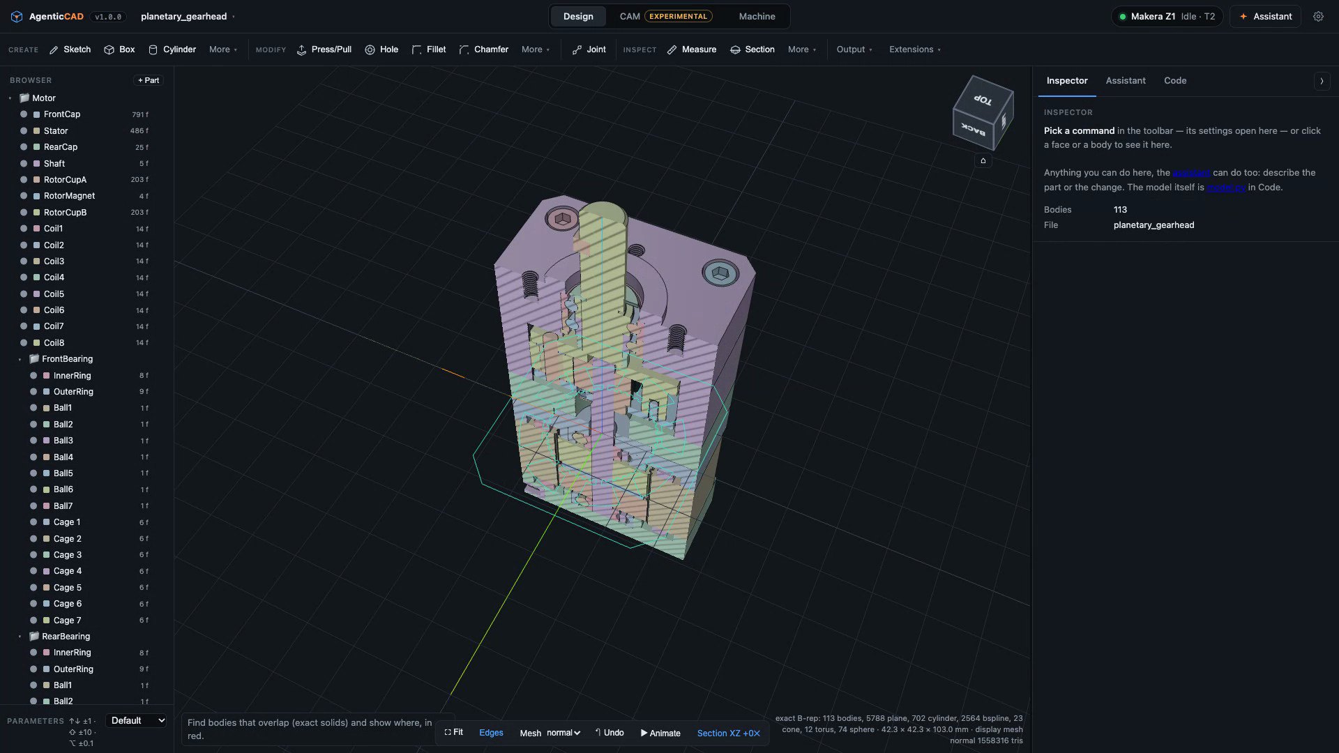
Press S: cut the model with a base plane or parallel to any flat face and slide through it; cut faces are hatched caps in each body's colour. Press J: exact overlap volumes for every pair of bodies, with thread engagement listed separately, and the overlap shown in red. The agent runs the same check before it calls an assembly done.

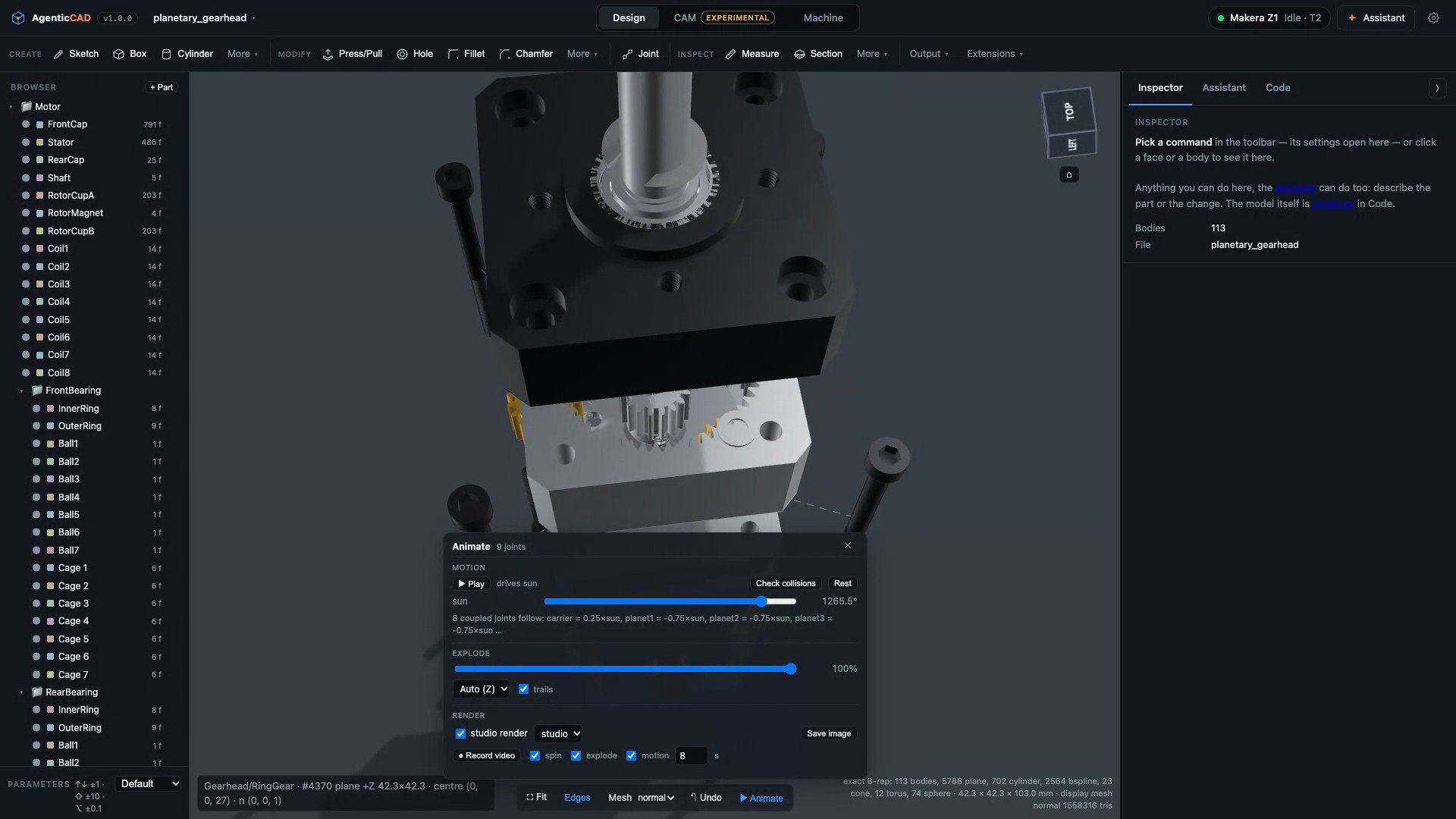
Exploded view: automatic, by sub-assembly then part, with trail lines

Make it move

Joints live in the script: revolute, slider, couple for gear ratios and racks, drive to play. ▶ Animate has a slider for every free joint, plays the drive, and explodes the assembly automatically or by your offsets. Check collisions sweeps the motion for parts that hit each other.

Studio render: physically based materials, environment light, soft shadows

Render it

One click for a studio render: about thirty materials (appearance in the script, sensible defaults from body names), environment lighting and soft shadows. Save a high-resolution image or record a video of the spin, the explode or the motion.

The sun drives the carrier at 4:1; planets ride the carrier; bearing balls run at cage speed

113 parts, one prompt

“Design a NEMA 17 planetary gearhead, 4:1, module 0.6…” The agent reached for the kit — kit.planetary_stage, kit.ball_bearing("688ZZ"), kit.socket_screw("M3", 40, real=True) — built it body by body, measured clearances, ran the interference check and fixed what it found. That design is an eval case in the repository: what the video shows is what the test grades.

Motion, explode and render in the docs → The Design Kit →
Going further

Reuse, import, connect, trust.

The things you reach for once the first parts are done.

Design Kit

63 ready-made standard parts the agent calls by name: ISO screws with real threads, ball bearings by designation with balls and cages, gears and planetary stages, NEMA steppers down to the coils, servos, boards, extrusions, springs, O-rings. Plus 27 design guides it reads before designing, and a per-workspace kit it adds its own notes and parts to.

Extensions

One Python file adds helpers, agent tools, build checks and panels. Hot-reloaded, listed in Settings, and the agent writes them on request — see it happen.

Part library

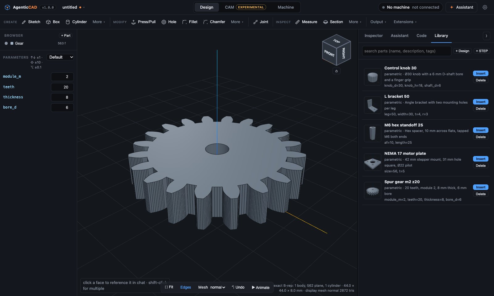
Parametric script parts and exact STEP parts with thumbnails and tags. Insert from the Browser with + Part, save any body to it, and the agent searches it before modelling a standard part.

STEP import

Drop a .step on the viewer: as a new body in the current design, as a new design, or straight into the library. Exact, and referenced from the script so the design stays reproducible.

Reference images

Attach photos, sketches or old drawings to a message. The agent reads them directly; the dimensions you type override what it estimates.

Choose the model, plug in MCP

Claude Opus 5.5 by default. Settings for the model, effort, max steps, thinking summaries, web tools, standing instructions and MCP servers (stdio, http, sse) with live connection status. Restart the session in place.

Design as script

Rename, delete and add bodies, set parameters, sketch blocks and toolbar operations are AST rewrites of the same file. Every build is kept in history; Undo steps back through it.

Tested, and evaluated

295 unit and API tests run in about three minutes with no Claude calls. 39 agent evals run the real agent headless and grade geometry, programs, panels and answers deterministically, with cost and steps per case.

Library tab — parametric and STEP parts
Part library tab with parametric parts and thumbnails
Step 4 · When the app lacks a tool

The agent extends the app itself.

Ask for a mass-and-cost estimator, a bolt-pattern tool, a thin-wall check or a hole report, and the agent writes one Python file. It can add helpers every design script can call, tools the agent itself can call, checks that run after every build, and panels: sliders, numbers, pickers that take a face or a body from the viewer, tables whose rows select the geometry they describe, buttons. Panels are declared, not coded, so they render from the toolbar's Extensions menu with the app's own look and keep working across releases. Files hot-reload; Settings lists them, and a broken one shows as broken instead of breaking a design.

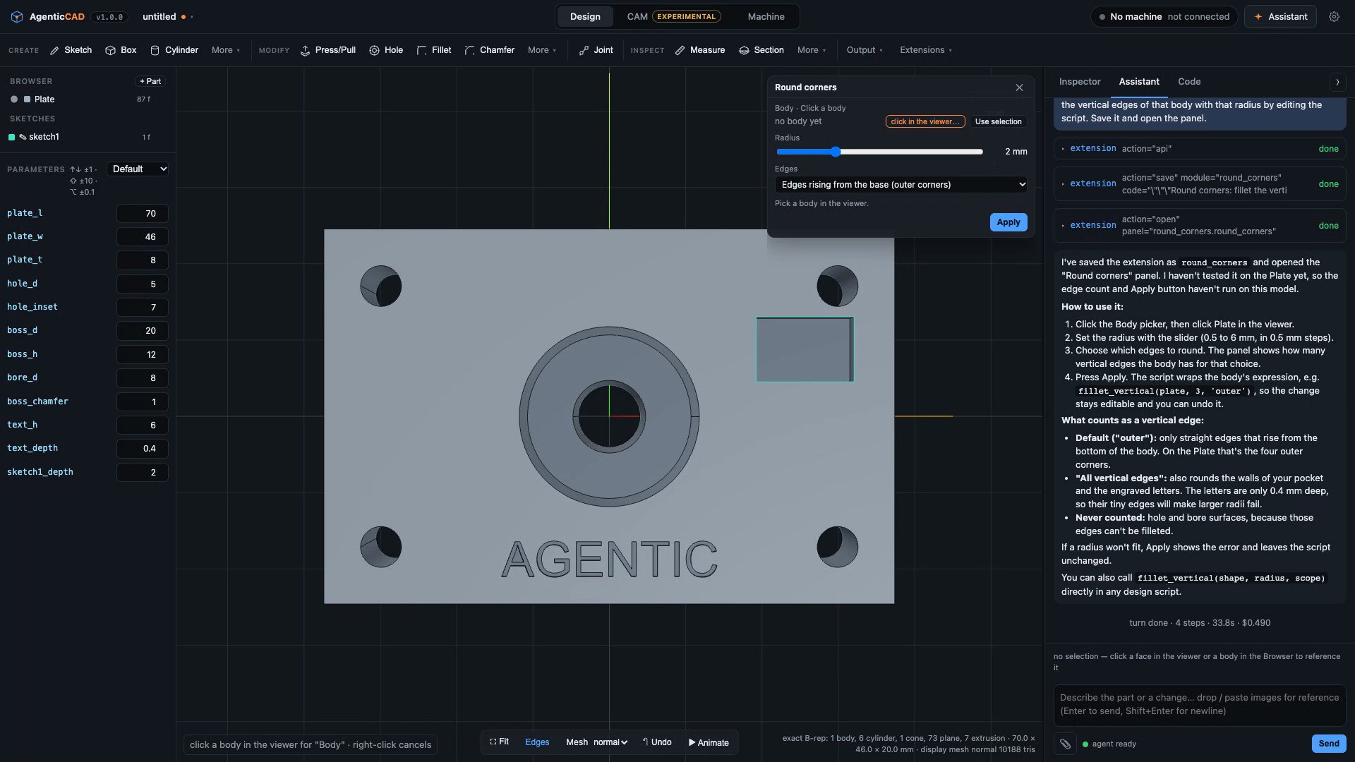
@panel("Round corners", icon="◜", description="Fillet the vertical edges of a body")
def round_corners(ctx):
    s = ctx.state
    body, radius = s.get("body"), s.get("radius", 2.0)
    info = ui.text("Pick a body in the viewer.", muted=True)
    if body:
        b = ctx.body(body)
        info = ui.kv([["Body", body], ["Vertical edges", len(_vertical_edges(b.shape))]])
    return ui.panel(ui.picker("body", "Body", what="body"),
                    ui.slider("radius", "Radius", radius, 0.5, 6, step=0.5, unit="mm"),
                    info, ui.button("Apply", call="round_corners_apply", primary=True))

That is the panel in the clip, as the agent wrote it during the recording (lightly abridged); its Apply wraps the body in a round_vertical_edges(plate, 3) helper it also defined. Built-in examples ship with the app: Parameters (every number as a live slider), Hole report, Bolt pattern.

Extensions in the docs →
Asked for a “Round corners” panel: picker, slider, Apply — written, saved and opened by the agent, then used
Experimental · CAM

CAM for your machine, simulated before it cuts.

Treat CAM as experimental. The toolpaths are geometrically correct and the post checks your machine's limits, but they are not yet optimised: expect long, conservative paths with many retracts, and simulate before you cut (the simulation checks the holder, nose and head against the stock and bed, and plays back on a model of your machine). Good for learning and for parts you inspect first; not yet a replacement for your CAM package. The modelling side is where AgenticCAD is solid today.

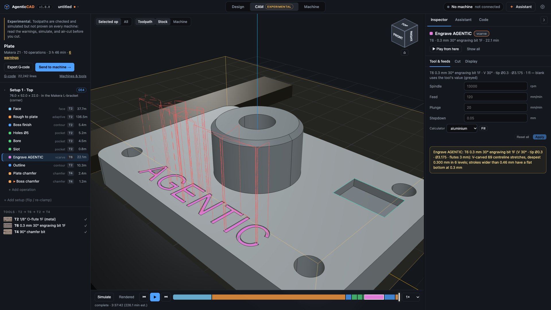
Describe the job the way you would brief a machinist and the agent writes a second script, cam.py, against a small API: face, contour, pocket, adaptive, drill, parallel3d, and new in 1.0 chamfer_edges and vcarve (letters cut along their centrelines, as deep as each stroke is wide). On the 4th axis, 1.1 adds rotary_profile (a hex, square or cam from round bar) and gear_teeth (involute teeth with a module cutter from the side of the blank, simulated to within 0.02 mm), with the chuck, jaws and tailstock checked in 3D on every move. Or click + Add operation in the CAM tree and skip the chat. The CAM workspace shows the program as a tree with the tools it needs in order, the Inspector edits each operation, and the timeline simulates and plays it back. The post (GRBL; Makera for the Z1 and Carvera Air; Haas; LinuxCNC) checks travel, spindle range, feeds and depth before you press run.

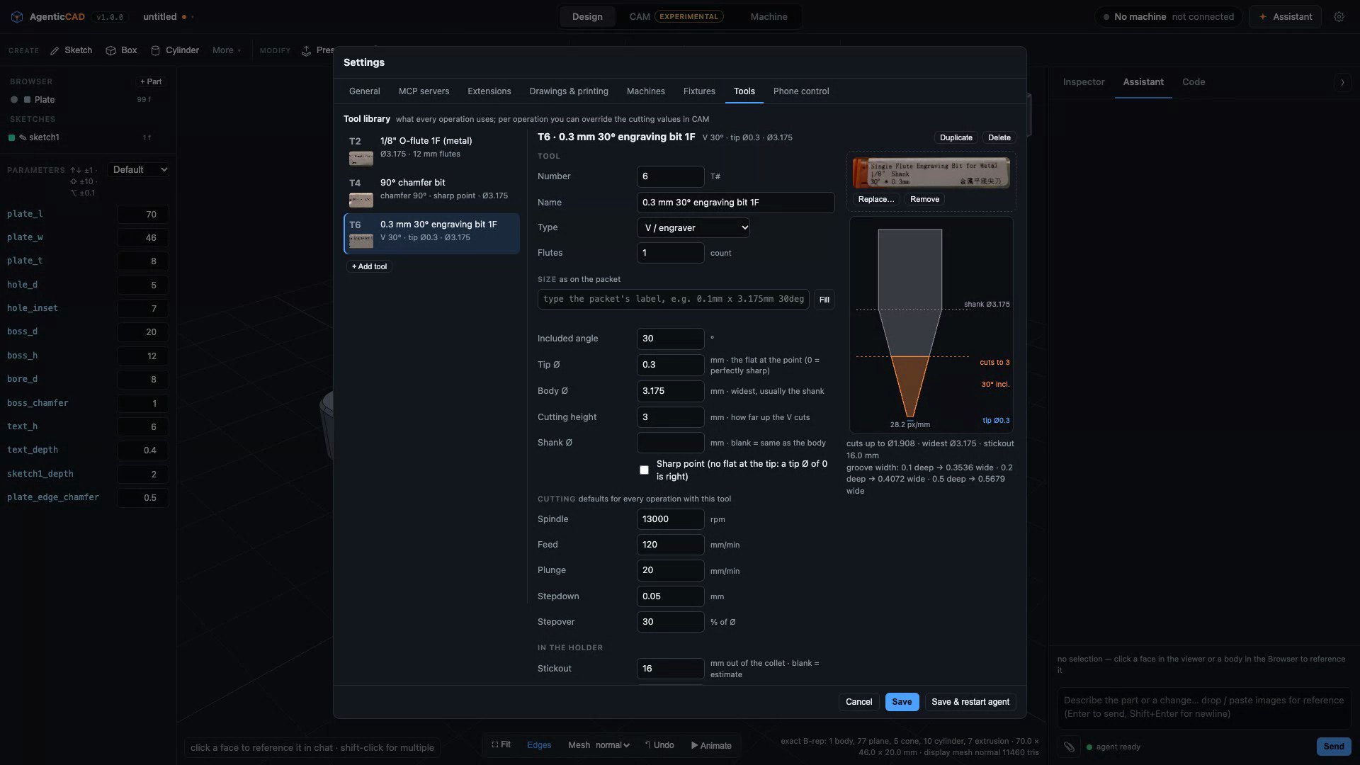
Your tools, as on the packet. Settings ▸ Tools describes each bit the way its packet does: a V-bit's angle and tip Ø, a ball nose's radius, the cutting height. Type the label and Fill does the rest; feeds are sized by the width actually cutting at depth; a cropped photo of the packet shows at every tool change, so you fit the right one.

Play the CAM tutorial (experimental) →
The CAM workspace: the program tree, the Inspector on each operation, the V-carve alone, then the simulation scrubbed
Settings ▸ Tools — sizes as on the packet, with its photo
The tool library: each tool with its packet photo, profile and sizes
Rendered simulation of the V-carve on the Makera Z1: a 0.3 mm 30° engraving bit cutting AGENTIC, the camera following the tool
plate.cam.py — toolpaths drawn from the real program
Toolpaths

The first lines of the exported G-code:

Experimental · Makera Z1

Then run it, one checked step at a time.

Experimental. Running programs on a machine is new. Air-cut every program first and stay at the machine with a hand near the emergency stop, especially through the tool changes.

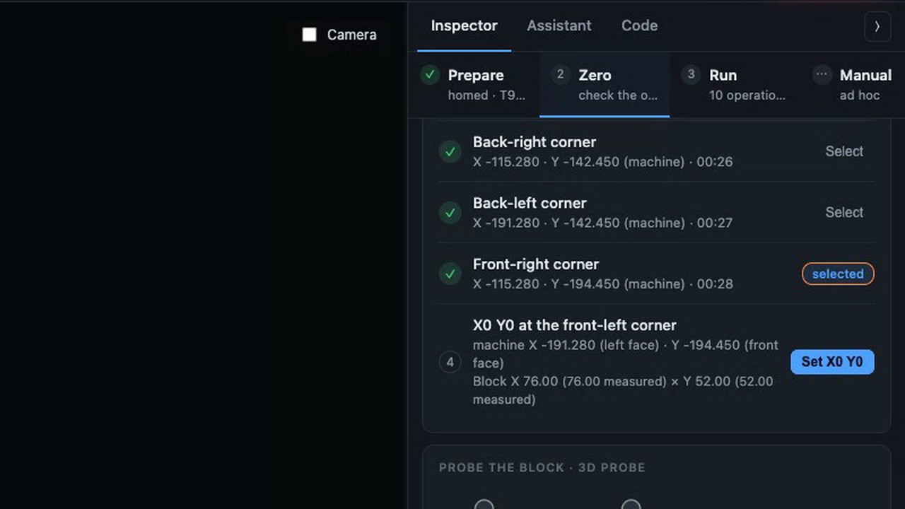
The Machine workspace connects to a Makera Z1 on your network: the status strip, the camera with a jog pad, and four steps. Prepare: home, change tool (the machine's own change, every tool and probe measured on the setter, the packet photo on the card). Zero: what the setup wants next to what set the origin this session; Find the block probes three corners of a block in the L-bracket and puts X0 Y0 on the front-left from the measured faces; on a rotary setup Zero on the 4th axis runs Makera's own 4th-axis Z probe for Z0 on the chuck centreline, sets Y0 from the controller's rotation offset, A0 and X0, one confirmed step at a time, with A on the DRO and the jog pad. Run: a readiness checklist, the program's operations in tool runs, an air cut first, progress op by op. Manual for everything else.

The assistant can work the machine too: hold, pause and STOP act at once; everything that moves waits as an approval card until you click Approve. Every spindle start lifts first, moves over the work, then comes down.

Prepare, Find the block and an air cut, recorded against the Z1 emulator at 4× speed (its camera is a test card, so the clip shows the steps)
Licensing

Free to make things. A$99 a year to make money with it.

Non-commercial · free

Personal projects, hobby making, research, education, and use by charities, schools and public institutions. Full source, every feature, no account, no telemetry. PolyForm Noncommercial 1.0.0.

Commercial · A$99 per user, per year

Using it in a business, in products or services, or as part of paid work. One licence per person who uses it, billed yearly in Australian dollars, same software. Buy online with the number of users you need; tax is added at checkout where it applies, and the receipt is your licence record, nothing to install or enter. Questions and volume or site licences: agenticcad@prodevelop.com.au. Terms of sale.

Buy licences · A$99 + tax per user / year

Tutorials

Watch a session, step by step.

Simulated replays of real sessions: the chat, the tool calls, the code and the exact meshes at every step were generated by the kernel, not drawn. Play them, pause them, scrub them.